注:本程序已验证可用,但只对本店模块做过适配测试,其他模块我们没法保证一定能用
实物参考链接 直戳跳转
一、资源说明

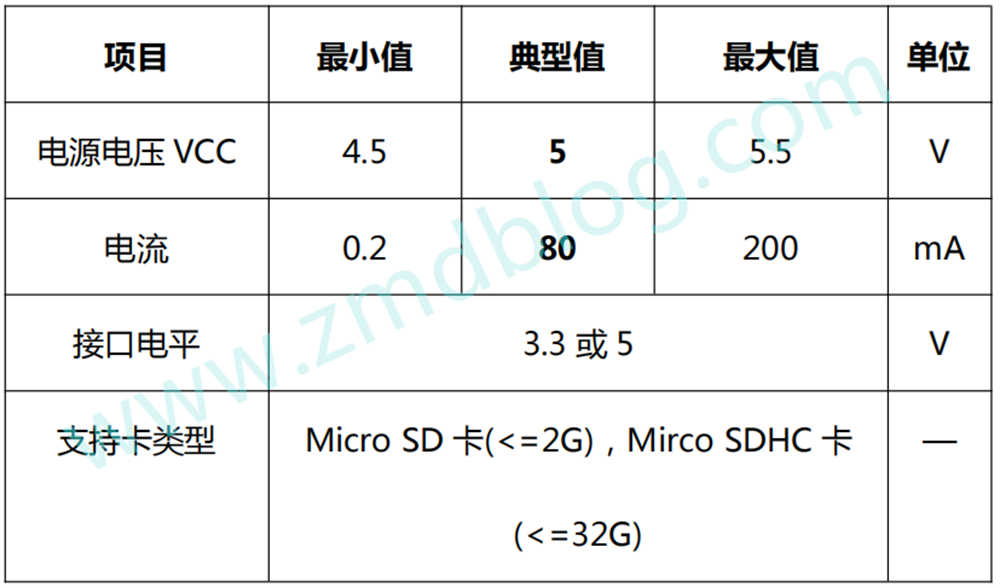
二、基本参数
参数

引脚说明

三、驱动说明
时序
SPI时序
对应程序:
/**
  * @brief  SPI_SD引脚初始化
  * @param  无
  * @retval 无
  */
void SPI_SD_Init(void)
{

  GPIO_InitTypeDef GPIO_InitStructure;

	/* 使能SPI引脚相关的时钟 */
 	SD_SPI_ALL_APBxClock_FUN ( SD_SPI_ALL_CLK, ENABLE );

  /* 配置SPI的 CS引脚,普通IO即可 */
  GPIO_InitStructure.GPIO_Pin = SD_SPI_CS_PIN;
	GPIO_InitStructure.GPIO_Speed = GPIO_Speed_50MHz;
  GPIO_InitStructure.GPIO_Mode = GPIO_Mode_Out_PP;
  GPIO_Init(SD_SPI_CS_PORT, &GPIO_InitStructure);

  /* 配置SPI的 SCK引脚*/
  GPIO_InitStructure.GPIO_Pin = SD_SPI_SCK_PIN;
  GPIO_Init(SD_SPI_SCK_PORT, &GPIO_InitStructure);


  /* 配置SPI的 MOSI引脚*/
  GPIO_InitStructure.GPIO_Pin = SD_SPI_MOSI_PIN;
  GPIO_Init(SD_SPI_MOSI_PORT, &GPIO_InitStructure);

  /* 配置SPI的 MISO引脚*/
  GPIO_InitStructure.GPIO_Pin = SD_SPI_MISO_PIN;
	GPIO_InitStructure.GPIO_Mode = GPIO_Mode_IN_FLOATING;
  GPIO_Init(SD_SPI_MISO_PORT, &GPIO_InitStructure);
  /* 停止信号 FLASH: CS引脚高电平*/
  SPI_SD_CS_1;


}

//********************************************
void SD_2Byte_Write(uint16_t IOData)
{
	uint8_t BitCounter;

	for (BitCounter=0;BitCounter<16;BitCounter++)
	{
		SD_SPI_SCK_0;//CLK Low
		DelayUs(5);
		if(IOData&0x8000)//If the MSB of IOData is 1, then Do=1, else Do=0.
			SD_SPI_MOSI_1;//Do High
		else
			SD_SPI_MOSI_0;//Do Low

		SD_SPI_SCK_1;//CLK High
		DelayUs(5);

		IOData=IOData<<1;//Because the MSB is transmitted firstly, shift to next lower bit.
	}
}
//********************************************
void SD_Write(uint16_t IOData)
{
	uint8_t BitCounter;
	IOData=IOData<<8;

	for (BitCounter=0;BitCounter<8;BitCounter++)
	{
		SD_SPI_SCK_0;//CLK Low
		DelayUs(5);
		if(IOData&0x8000)//If the MSB of IOData is 1, then Do=1, else Do=0.
			SD_SPI_MOSI_1;//Do High
		else
			SD_SPI_MOSI_0;//Do Low

		SD_SPI_SCK_1;//CLK High
		DelayUs(5);

		IOData=IOData<<1;//Because the MSB is transmitted firstly, shift to next lower bit.
	}
}

//********************************************
uint16_t SD_2Byte_Read(void)
{
	uint16_t Buffer;
	uint8_t BitCounter;
	Buffer=0;

	for (BitCounter=0;BitCounter<16;BitCounter++)
	{
		SD_SPI_SCK_0;//CLK Low
		DelayUs(5);
		SD_SPI_SCK_1;//CLK High
		DelayUs(5);
		Buffer=Buffer<<1;//Because the MSB is transmitted firstly, shift to next lower bit.
		                 //Because the LSB will be damaged, we can not put this line under next line.
		if(READ_SD_SPI_MISO)
			Buffer++;//If SPI_Din=1 then the LSB_of_Buffer=1.
	}

	return Buffer;
}

//********************************************
uint16_t SD_Read(void)
{
	uint16_t Buffer;
	uint8_t BitCounter;
	Buffer=0xffff;

	for (BitCounter=0;BitCounter<8;BitCounter++)
	{
		SD_SPI_SCK_0;//CLK Low
		DelayUs(5);
		SD_SPI_SCK_1;//CLK High
		DelayUs(5);
		Buffer=Buffer<<1;//Because the MSB is transmitted firstly, shift to next lower bit.
		                 //Because the LSB will be damaged, we can not put this line under next line.
		if(READ_SD_SPI_MISO)
			Buffer++;//If SPI_Din=1 then the LSB_of_Buffer=1.
	}

	return Buffer;
}
四、部分代码说明
接线引脚定义
需要自定义引脚可在此处更改,STM32要自定义引脚的话也要注意引脚时钟使能的更改
1.1、STM32F103C8T6+TF卡模块
#define      SD_SPI_ALL_APBxClock_FUN       RCC_APB2PeriphClockCmd
#define      SD_SPI_ALL_CLK                 RCC_APB2Periph_GPIOB


#define      SD_SPI_CS_APBxClock_FUN        RCC_APB2PeriphClockCmd
#define      SD_SPI_CS_CLK                  RCC_APB2Periph_GPIOB
#define      SD_SPI_CS_PORT                 GPIOB
#define      SD_SPI_CS_PIN                  GPIO_Pin_6

//SCK引脚
#define      SD_SPI_SCK_APBxClock_FUN       RCC_APB2PeriphClockCmd
#define      SD_SPI_SCK_CLK                 RCC_APB2Periph_GPIOB
#define      SD_SPI_SCK_PORT                GPIOB
#define      SD_SPI_SCK_PIN                 GPIO_Pin_7
//MISO引脚
#define      SD_SPI_MISO_APBxClock_FUN      RCC_APB2PeriphClockCmd
#define      SD_SPI_MISO_CLK                RCC_APB2Periph_GPIOB
#define      SD_SPI_MISO_PORT               GPIOB
#define      SD_SPI_MISO_PIN                GPIO_Pin_8
//MOSI引脚
#define      SD_SPI_MOSI_APBxClock_FUN      RCC_APB2PeriphClockCmd
#define      SD_SPI_MOSI_CLK                RCC_APB2Periph_GPIOB
#define      SD_SPI_MOSI_PORT               GPIOB
#define      SD_SPI_MOSI_PIN                GPIO_Pin_9
五、基础知识学习
STC89C52RC程序下载 直戳跳转
STM32F103C8T6程序下载
1、串口下载 直戳跳转
2、ST-LINK下载 直戳跳转
3、J-LINK下载 直戳跳转
4、DAP-LINK下载 直戳跳转
OLED0.96程序说明 直戳跳转
串口助手下载与使用
1、安信可调试助手使用 直戳跳转
2、 sscom33串口调试助手使用 直戳跳转
3、STC-ISP串口调试助手使用 直戳跳转
六、视频效果展示与程序资料获取
实物参考链接 直戳跳转
七、注意事项
1、VCC GND请勿接反,接反易烧
2、OLED显示异常时,排除接线接触不良
八、接线说明
可参考程序main.c最上面接线说明